Independent verification of every system that keeps the lights on.
HV and LV systems, critical power and life safety, from installation checks through to integrated systems testing. Fourteen disciplines, one accountable team.
Critical power & life safety
The systems that keep a facility running when the grid fails, and keep people safe when something goes wrong. We prove them under real load.
UPS load testing
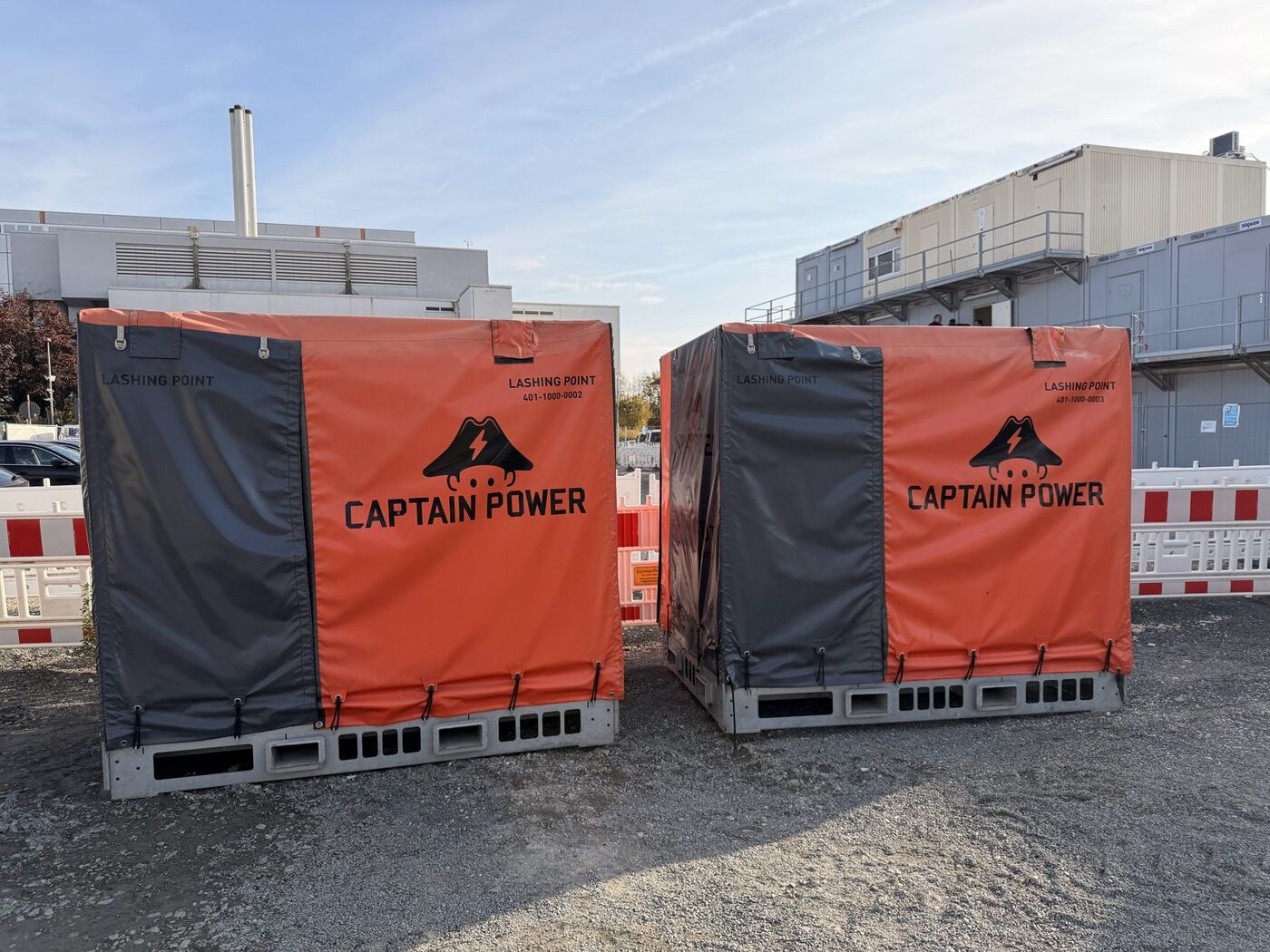
Step-load and full-load testing of UPS modules using calibrated resistive load banks. We verify output regulation, transfer to and from static bypass, and battery autonomy against design. Alarms are checked through to the BMS.
IEC 62040-3 · battery discharge & impedance · power-quality logging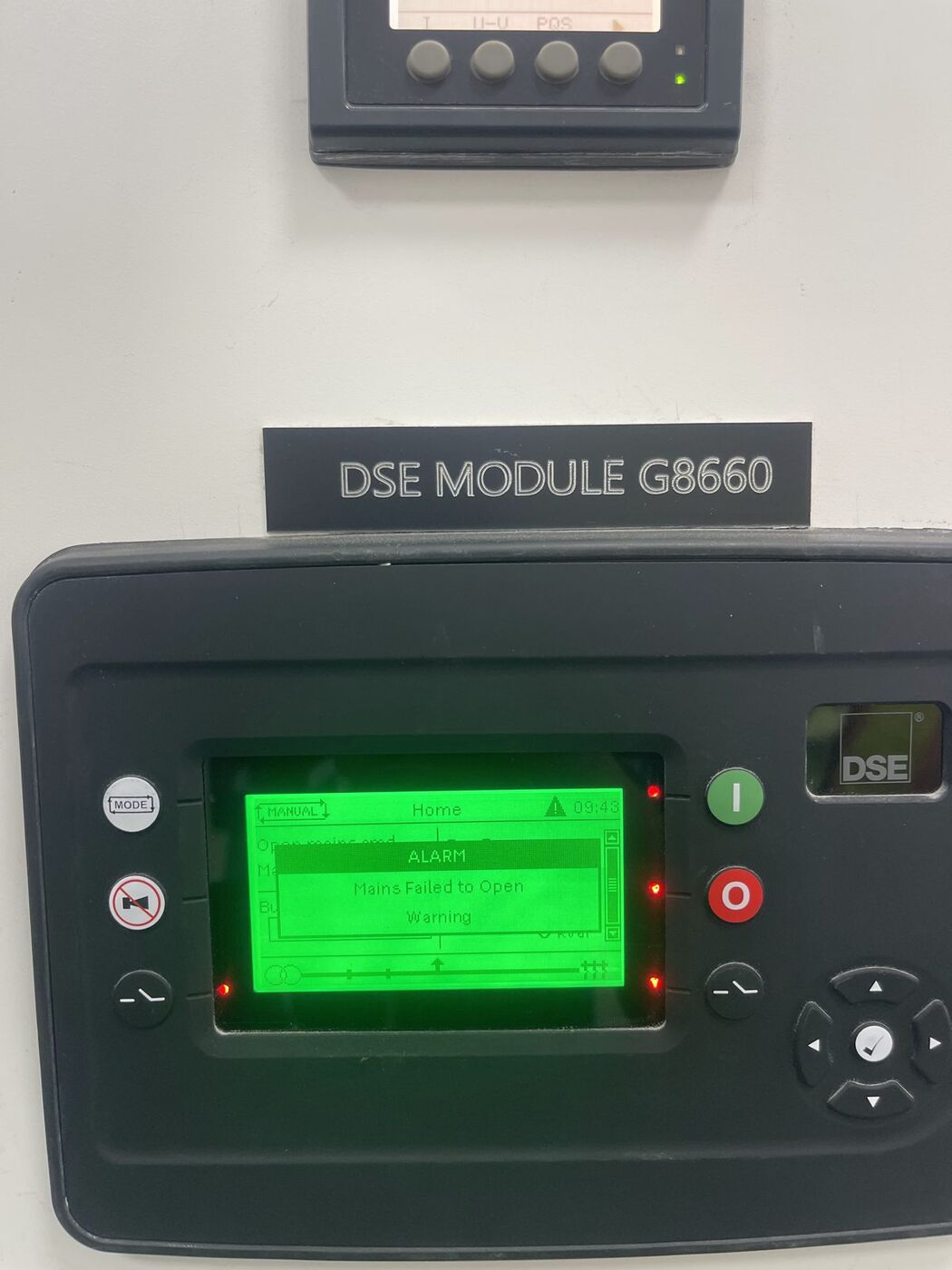
02Generator load testing
Load-bank runs from part load to full load with step-load response. We verify voltage and frequency recovery, ATS changeover, synchronising, and cooling performance under sustained load.
ISO 8528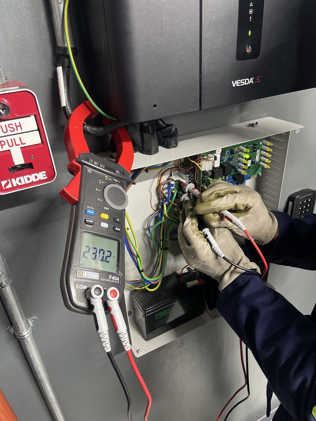
03Fire system testing
Cause-and-effect testing of detection, aspirating smoke detection (VESDA) and alarm panels. Includes the interfaces that trip power, release suppression and report to the BMS.
Cause & effect matrix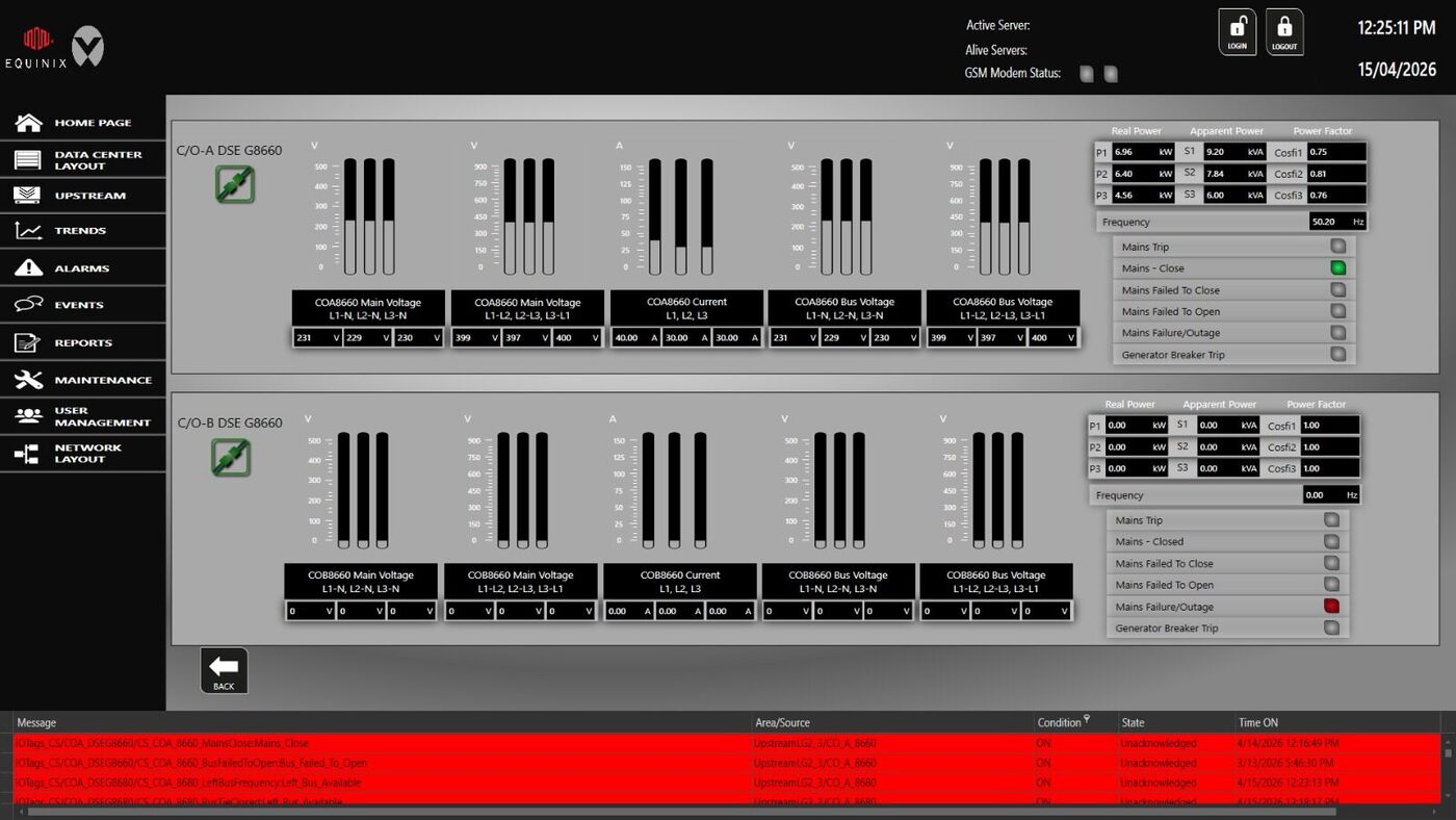
04Point-to-graphic testing
Point-by-point proof that every field signal shows correctly on the BMS or EPMS graphic, including breaker status, meter values and alarms. We check naming, scaling and alarm priority.
BMS · EPMS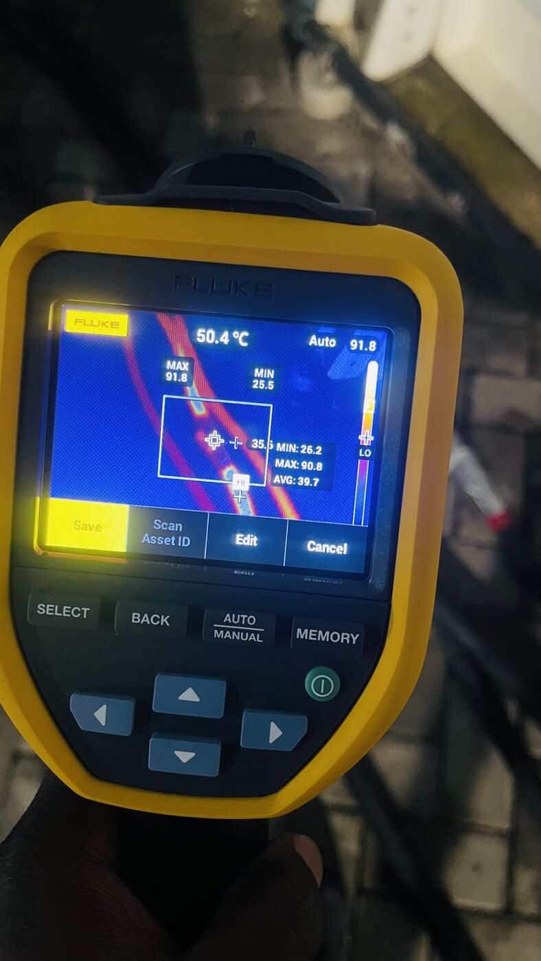
05Thermal imaging
Infrared surveys of switchgear, busbars, terminations and UPS systems under load. Hot joints and overloads are found before they fail, and each finding is ranked by temperature rise.
Radiometric survey reportsElectrical integrity testing
Pre-energisation and acceptance tests that prove every transformer, cable, joint and protective device is sound, from MV switchgear down to final circuits.


06Transformer winding resistance
DC resistance of each winding on every tap position. This finds loose connections, broken strands and tap-changer faults.
IEC 60076-107Secondary injection
Relays and electronic trip units tested by injection. Pickup and trip times are proven against the protection coordination study.
IEC 60255 · settings verification08Torque verification
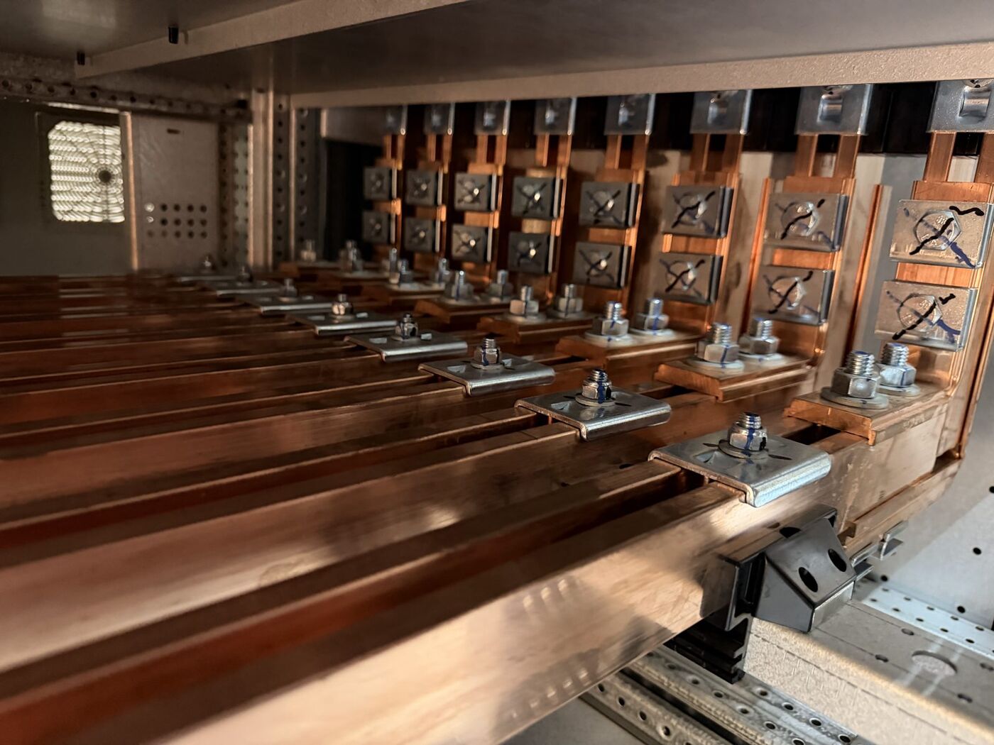
Busbar joints and cable terminations checked with calibrated wrenches against manufacturer values, then marked and recorded.
Manufacturer torque tables09Insulation resistance
IR and polarisation index up to 10 kV on cables, switchgear, transformers and motors.
IEC 60364-6 · IEEE 4310Ductor (contact resistance)
Micro-ohm resistance of breaker contacts, busbar joints and connections, measured with a high-current DLRO.
IEC 62271-111Earth fault loop impedance
Zs measured at boards and final circuits to prove protective devices disconnect within the required time.
BS 7671 · IEC 60364-612Dielectric (hi-pot)
Power-frequency withstand tests on switchgear, busbar trunking and assemblies before energisation.
IEC 61439 · IEC 62271-113VLF cable testing
Very-low-frequency withstand testing of MV cables after installation and jointing.
IEEE 400.214General electrical works
Terminations, remedial works, snag close-out and installation support that keep the programme moving.
HV · LV · controlsLevel 2 to Level 5.
Every result recorded, every defect tracked to close-out.
We issue test sheets and certificates against your inspection and test plan, ready for client witness and handover.